GETTING STARTED

Caution CAUTION:
The meter has no power-on switch, so it will be in operation as soon you apply power.

If you power off/on the meter momentarily shows the following: "idP" for model type, "codE", and "rxx" for the micro controller revision code.

Note: Keep track of revision code for future reference.

CHANGING CONFIGURATION JUMPERS

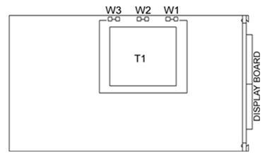
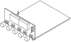
The S1, S2 and S3 DIP switches are at the front of the meter near the digital display. The S4 DIP switch is on side of the main board (refer to Figure 3╨3). Remove the lens cover to access these jumpers.

S1 - S4 DIP Switches (Defaults in bold & Italics) Table 3-1
Jumper
Description
S1
Installed: 10 volt excitation
Removed: 24 volt excitation*
S2
Installed: Front-panel buttons locked out
Removed: All buttons operable
S3
Installed: PEAK shows when /MAX button is pushed
Removed: VALLEY shows when /MAX button is pushed
S4
Installed: Calibration enabled
Removed: Calibration disabled

FRONT OF THE METER
S1 - S4 Jumpers
Figure 3-1. S1 - S4 Jumpers
MOUNTING THE METER
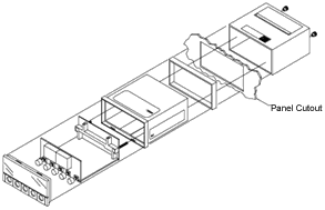
Meter Figure 3-2. Meter - Exploded View

1.
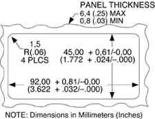
Cut a hole in your panel according to the dimensions specified in Figure 3-3.

2. Insert the meter into the hole. Be sure the front bezel is flush to the panel.

3. Proceed to Section
NOTE: Dimensions in Millimeters (Inches)

Panel Cut-Out
Figure 3-3. Panel Cut-Out
CONNECTING SENSOR INPUT
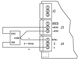
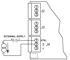
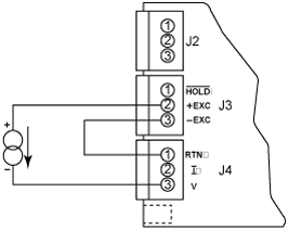
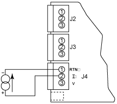
Figures 3-4 through 3-8 describe how to connect common sensor types.

3-Wire DC Voltage Input
Figure 3-4
3-Wire DC Voltage Input Connection with Internal Excitation
2-Wire DC Voltage Input
Figure 3-5
2-Wire DC Voltage Input Connections with External Excitation

4-20 mA Input Connections w/external excitation
Figure 3-6
4-20 mA Input Connections with External Excitation

4-20 mA Transmitter Hook-Up w/Internal Excitation
Figure 3-7
4-20 mA Transmitter Hook-Up with Internal Excitation
DC Current Input Connections with Current Source
Figure 3-8. DC Current Input Connections with Current Source

CONNECTING MAIN POWER
Connect the ac main power connections as shown in Figure 3-9.

 Main Power Connections - AC
Figure 3-9
Main Power Connections - AC

Connect the dc main power connections as shown in Figure 3-10.

 Main Power Connections - DC
Figure 3-10
Main Power Connections - DC


WARNING:
Do not connect ac power to your meter until you have completed all input and output connections. Failure to do so may result in injury

Table 3-2 shows the wire color and respective terminal connections for both USA and Europe.
ire color and respective terminal connections for both USA and Europe.

AC Power Connections Table 3-2
AC POWER
WIRE COLORS
EUROPE
USA
~ AC Line
Brown
Black
~ AC Neutral
Blue
White
~ AC Ground
Green/Yellow
Green
Help Price List Specifications Print Manual Manuals Home
 Home Home  Table of Contents TOC  Back Back  Next Next